The power company, or you, decide you need to de-energize a circuit. You rack out and remove your trusted 1960’s vintage breakers, of course you are suited up in the proper level PPE (Personal Protective Equipment). You then dust off your vintage ground and test device and install it in the cubicle. Connect the motor and step to the side, hoping that everything will be OK. The device is fully racked in with no explosions. You connect your “Chicken” switch, turn the selector switch to close. Walk as far as the chicken switch will allow and press “Close”.
All you can hear is the motor spinning and never turning off. You are extremely ticked off. There was a lot of work and sweat put into this entire process, and now you have to do it in reverse to remove the device. On top of that, you now have to figure out another safe way to ground the feeder cables. What do you do?
The breakers which are being referred to are General Electric’s 15,000 volt breakers from the 1950’s and 1960’s. These things are tanks! They weigh upwards of 1,000 pounds. The stabs are on the top of the breaker, and this breaker racks in and out vertically. If you haven’t seen them, they are quite the spectacle.
There are differences between the Ground and Test device, and an air circuit breaker. But if we are simply looking at the operating principle, they are generally the same. They contain the same parts, i.e. charging motor, close and trip coil, contact stabs. A different operation would be the way breakers charge the closing spring and the way the ground and test device charges it’s spring.
A breaker, when racked into a cell, charges the springs immediately and waits for a close command via a control switch of some sort. A ground and test device does not sit with the springs charged. It waits for an operation to close, charges the springs and discharges they to close the device, then sit with them discharged. Here is a normal operation of the spring charging mechanism of a ground and test device:
This video was recorded after the issue was repaired, displaying the proper way a ground and test device closes.
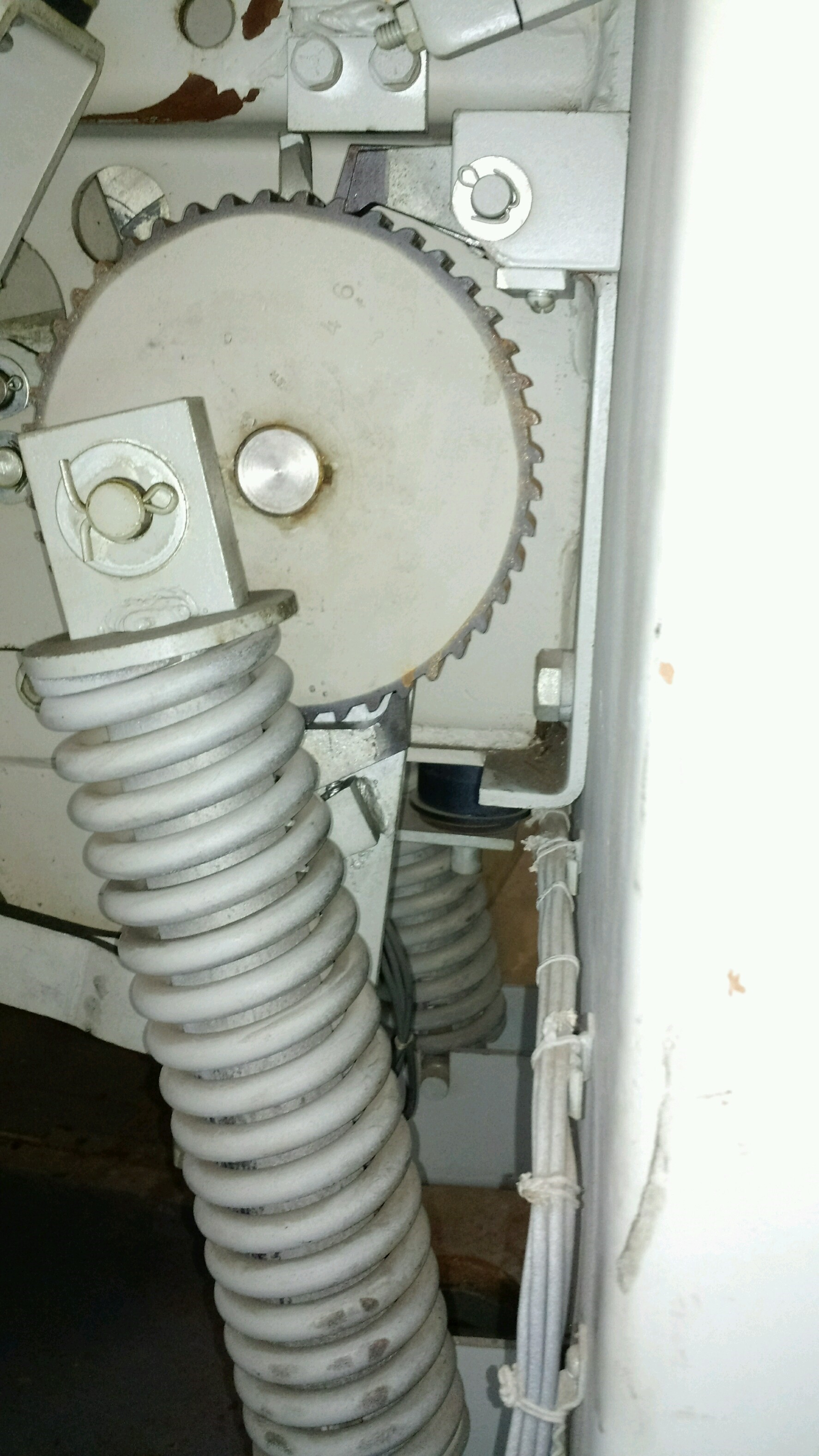
In the photo above, you can see the charging spring, the spring charging gear, the latching pawl (top of gear), and the driving pawl (bottom of gear). The driving pawl is the part that pushes the gear, to rotate it to spin. The latching pawl, catches the gear. So when the driving pawl moves backward to get another push, the gear doesn’t spin and release all of the pressure on the spring.
As you can see on the driving pawl, there is a spring that pushes back the pawl into the gear. The spring has apparently become weak and cannot push the pawl back into the gear. So during a charging operation, the pawl moves back and forth, but not engaging the gear.
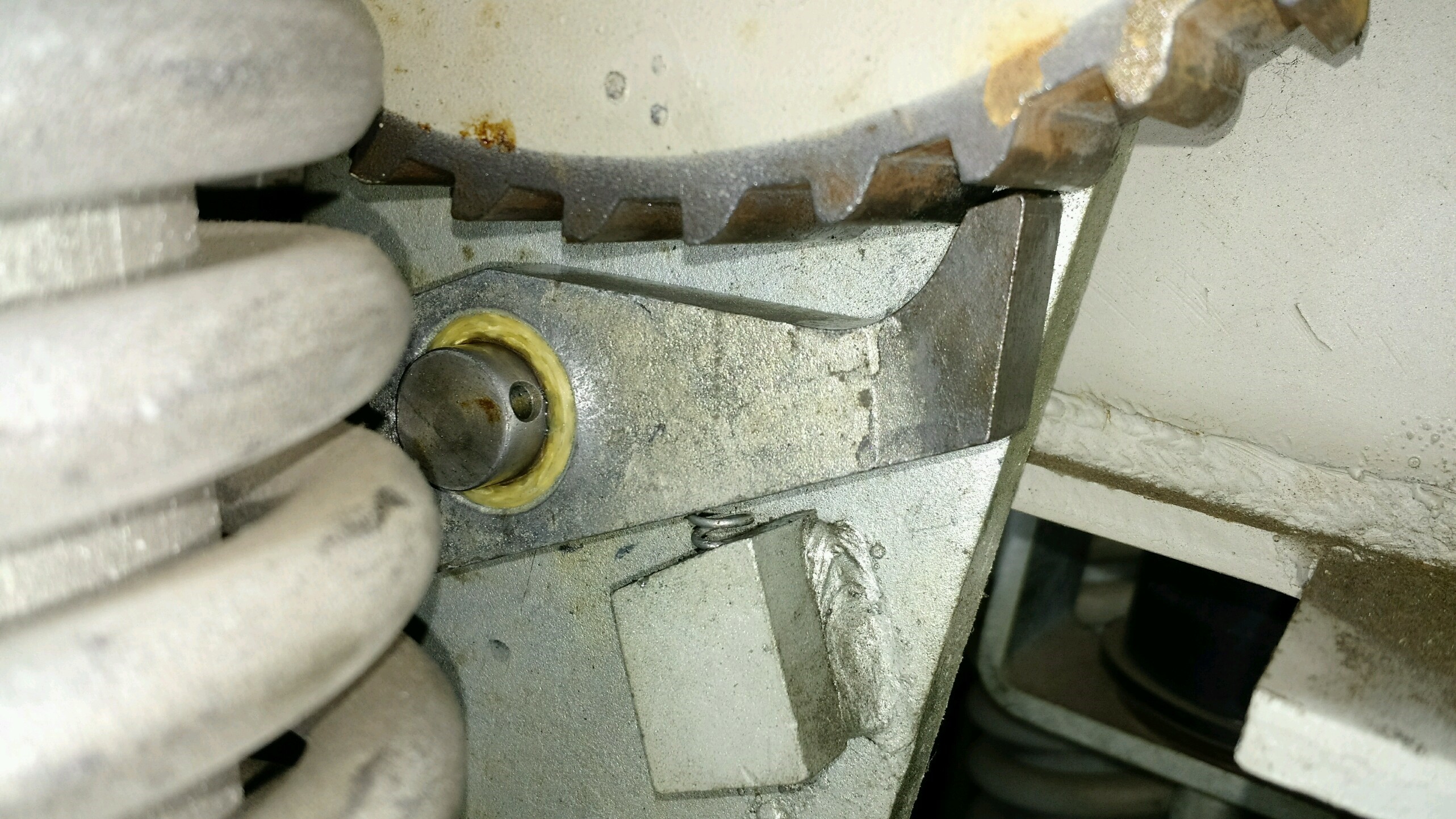
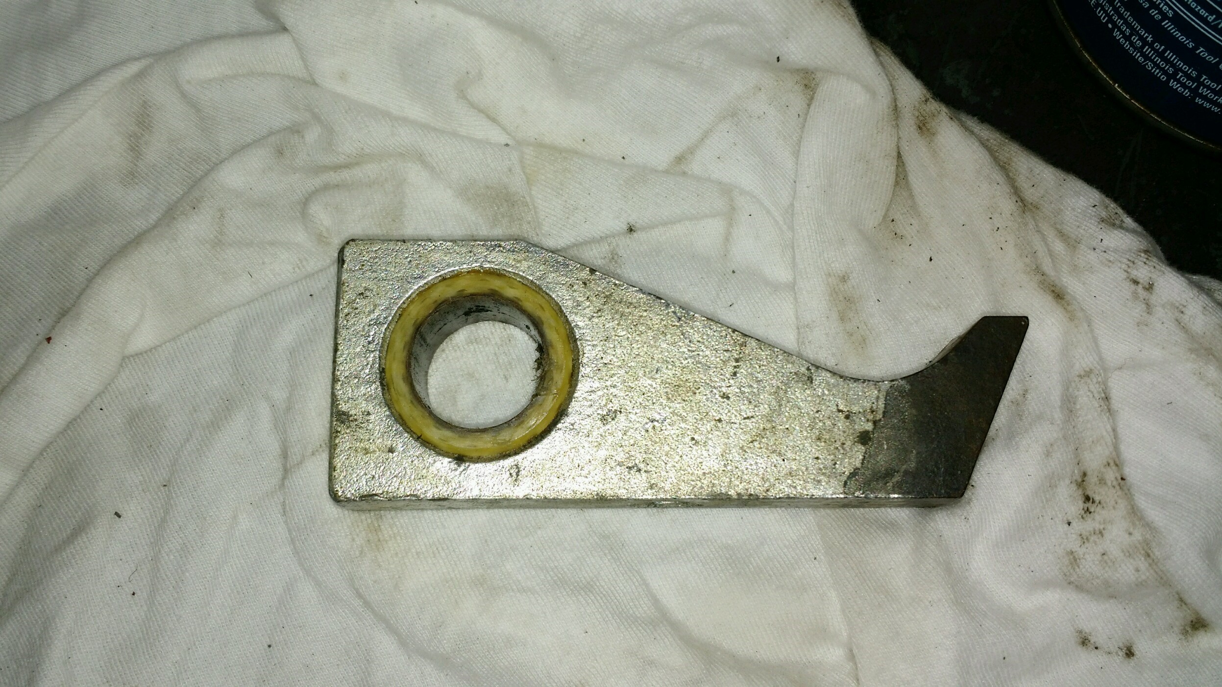
This is a closeup of the driving pawl. As you can see, the yellowish colored material, rides on a steel shaft. The purpose of this material, is to ensure there is no grinding of metal on metal contact. It is a hard, porous, fibrous material. Over the years of lubricating, this fiber absorbs any oil lubricants and expands. It has expanded to the point that the spring can no longer push the pawl back to engage the gear. So what do you do?
Grab a drill bit. We are only talking about removing maybe 1 millimeter off of the fiber. We want the pawl to move freely on the steel shaft, but not be sloppy and cause anymore issues. Parts for these breakers are not readily accessible. Fixing what you have is the only option when it is a matter of getting a breaker back online, or waiting multiple days for parts.
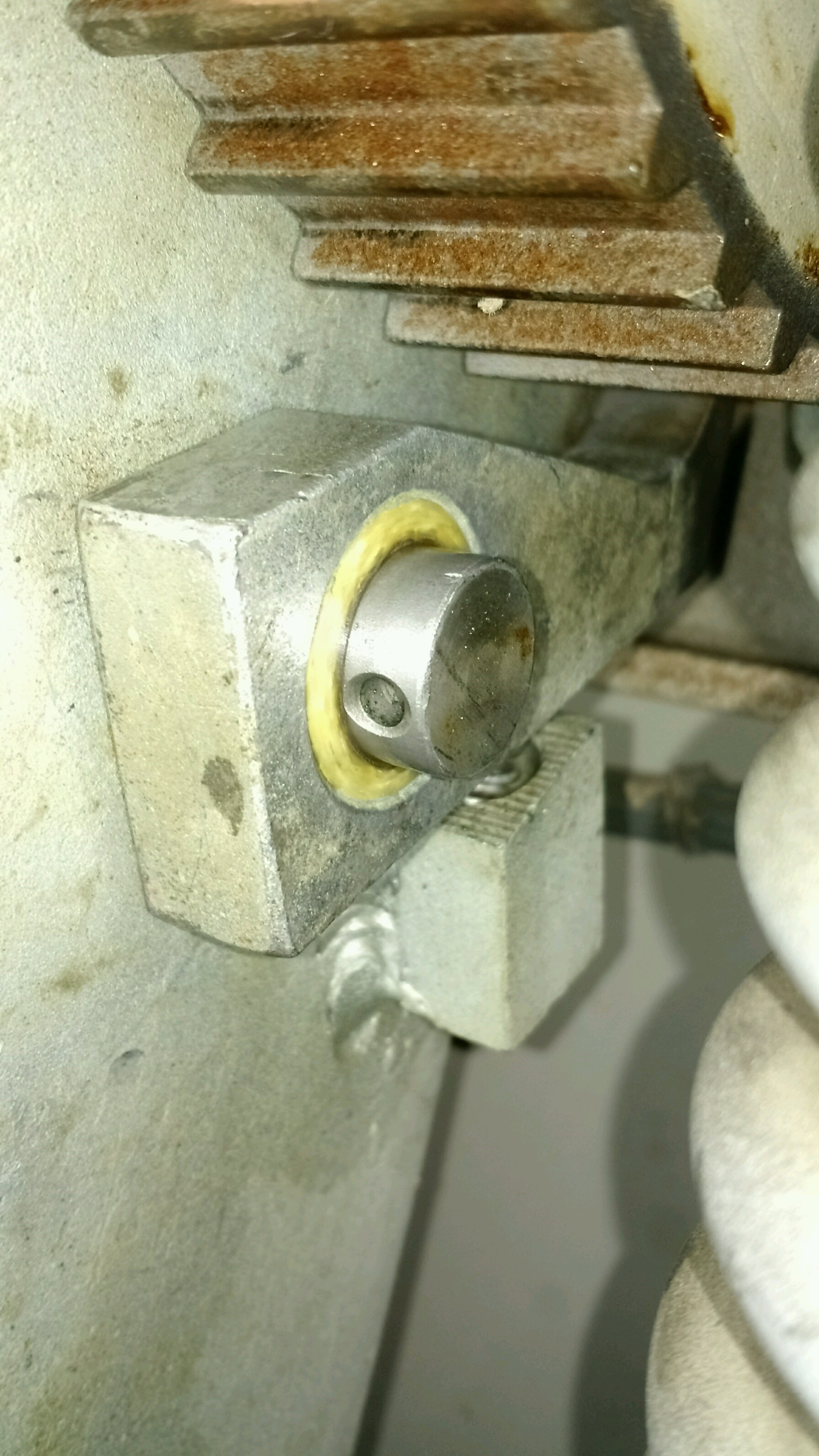
This is another view. What you are not seeing, is that I have removed the washer and cotter pin from the shaft, to give a good visual.
I hope this is informative enough to get you out of a bind, when you need it most.


