Medium Voltage Cables
Electrical wire is an integral part of our lifestyle. Whether you care to notice or not, copper/aluminum conductors are everywhere. They provide power to every business and home that wishes to be connected.
Most of the time, people who aren’t in the electrical trade, tend to see overhead power lines. Those consist of telephone poles and uninsulated wire. But often times, cables need to be routed underground, to get past that overpass. Or to make the electrical system more reliable. Wire that is run underground cannot be constructed in a way to only have a bare conductor entering the earth.
We, as electricians, put a lot of effort into grounding and bonding. This is to protect people and equipment. This can go into much detail, but just know that electrical conductors must be constructed in a manner to remain insulated from earths potential.
If you aren’t familiar with a medium voltage cable, I will try to break it down for you.
Medium Voltage Cable Components

If we look at a medium voltage single conductor cable, as pictured above, you can see each layer that makes up the entire cable. The thickness of the red insulation will be thicker depending on the voltage class, as well as possibly a different color. It could even be a different type of cable all together (EPR, XLP, LEAD, etc.)
PVC Outer jacket:
The outermost layer of the cable is the jacket. The function of the jacket is to protect the internal components of the cable from external physical forces (i.e. water) and chemical deterioration.
Copper Tape Shield:
The copper tape shield protects the cable itself by confining the cable’s dielectric field and providing symmetrical radial distribution of voltage stress. This limits the stress concentration at any one insulation point. It also helps dissipate heat away from the current-carrying conductor.
The copper tape shield also helps to protect the user from shock hazards and increases cable reliability by draining off energy that might otherwise cause partial discharge in cables. The shield also carries fault current in the event of a fault.
Semiconductor:
The semiconductor layer is between the Copper Tape Shield and the insulation. One function of the semiconductor is to create a smooth surface for even charge dispersion. It is an important part of a cable system used to increase the service life of the cable.
Insulation:
As pictured above, the insulation is the reddish rubber material. This is called insulation. This particular insulation is ethylene propylene rubber, which is abbreviated as EPR. This is one of the most common types of cables being installed today.
This is a protective layer, which allows medium-voltage cable to be laid and installed without the flow of electricity grounding to any adjacent structures. The insulation is the barrier that contains the electrons and is sort of like the wall of a pipe.
Strand Semiconductor:
This is the thin black layer, closest to the copper conductor that serves a very important function. The semiconductor nature of this material allows it to equalize the charge across the smooth surface of the relatively bumpy conductor. This is important to reduce distress placed on the insulation and significantly increases the life expectancy of the insulation.
Copper Conductor:
This is the medium of which power is supplied to customers or distributed to different locations. Copper is a good conductor of electricity, right behind silver and gold. This is how voltage and amperage get distributed to be consumed.
Medium Voltage Terminations
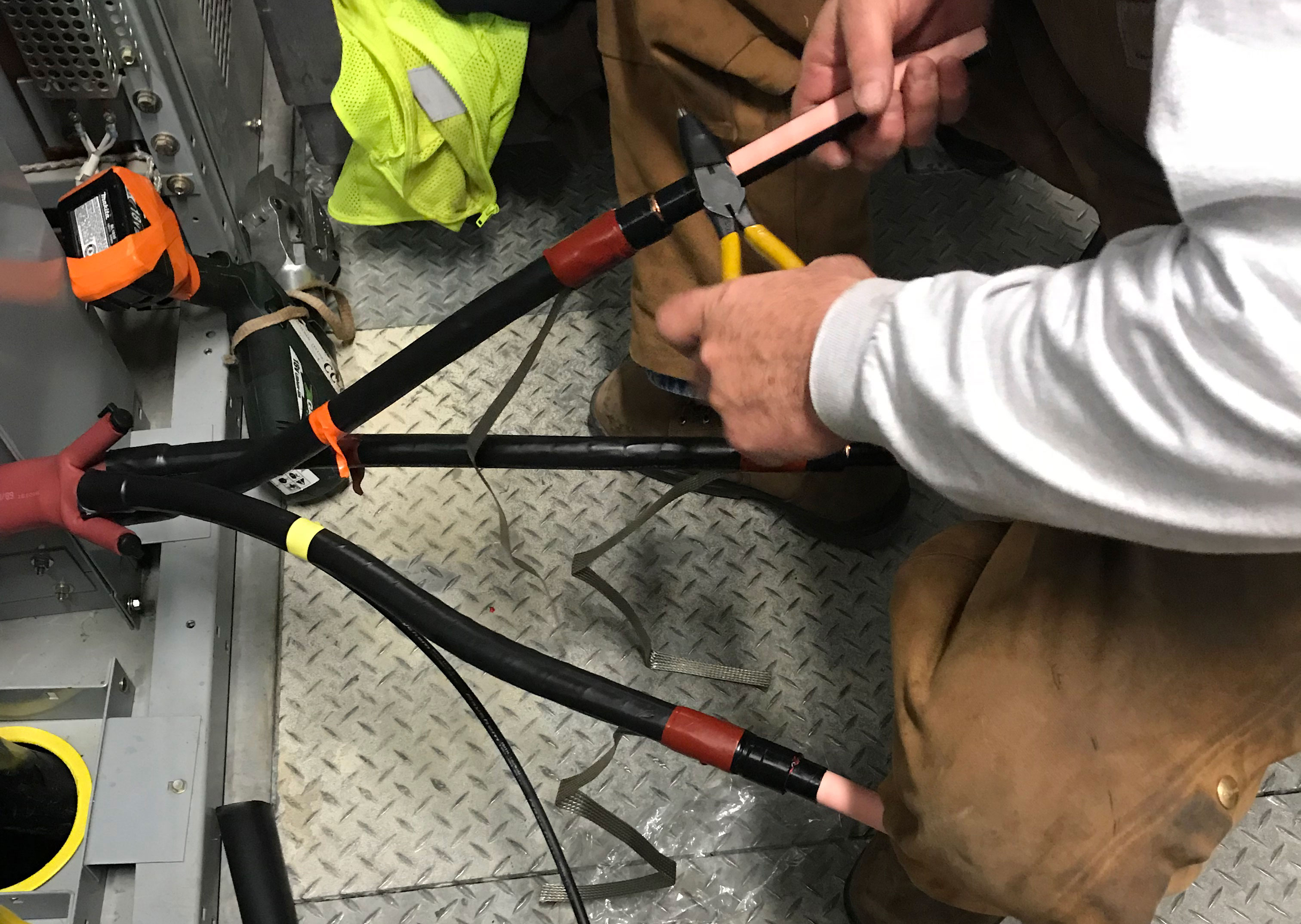
Terminations are a very important part of a cable system. If they are done improperly, the cable could fault, causing thousands of dollars worth of damage, or even personal injury. Craftsmanship is also a major factor of a termination.
While some may argue “a kit is a kit, slap it on and go to the next”, we need to take care while performing the task of terminating. Cleanliness is another major factor. Dirty hands can leave residue on the insulation that must be clean. This can lead to insulation breakdown via tracking.

Specific distances are measured when performing cutbacks. If the proper measurements are not used, creep-age distances cannot be maintained.

Scoring the semiconductor. Extra care must be take to ensure the knife isn’t penetrating the insulation. Experienced hands use knives.
Removal of the semiconductor
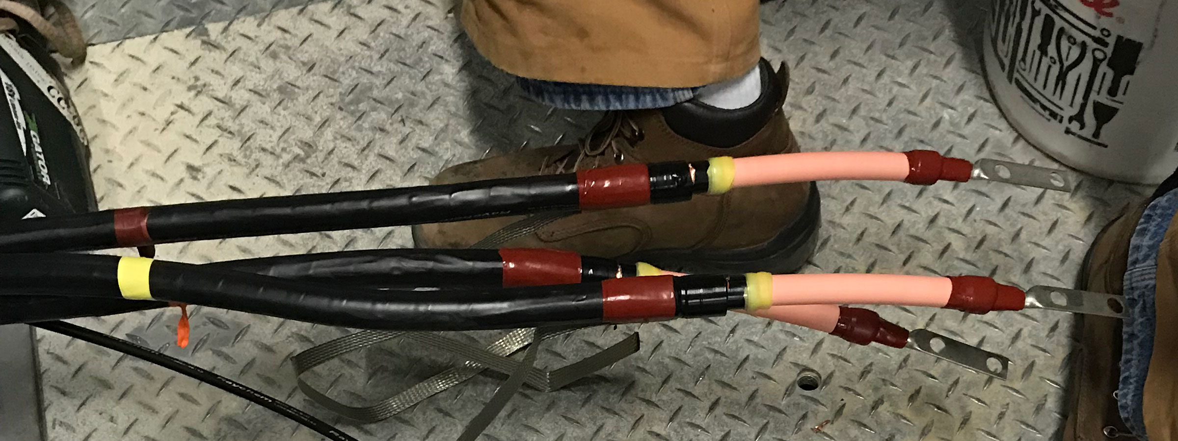
Cables are ready for the Red non-tracking heat shrink tubing.
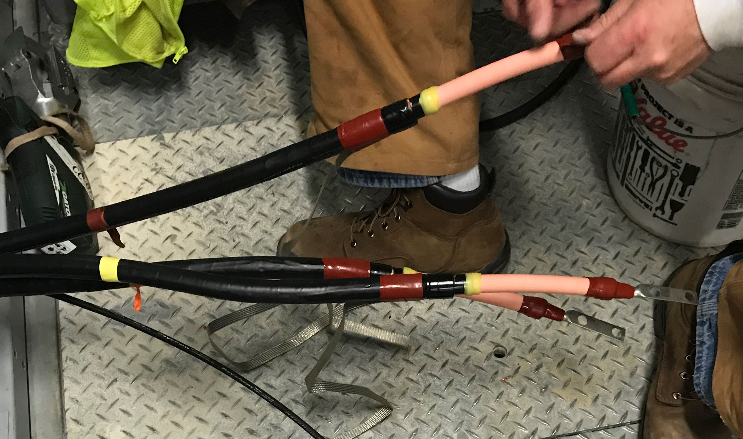
Red waterproofing mastic and yellow stress relief mastic.
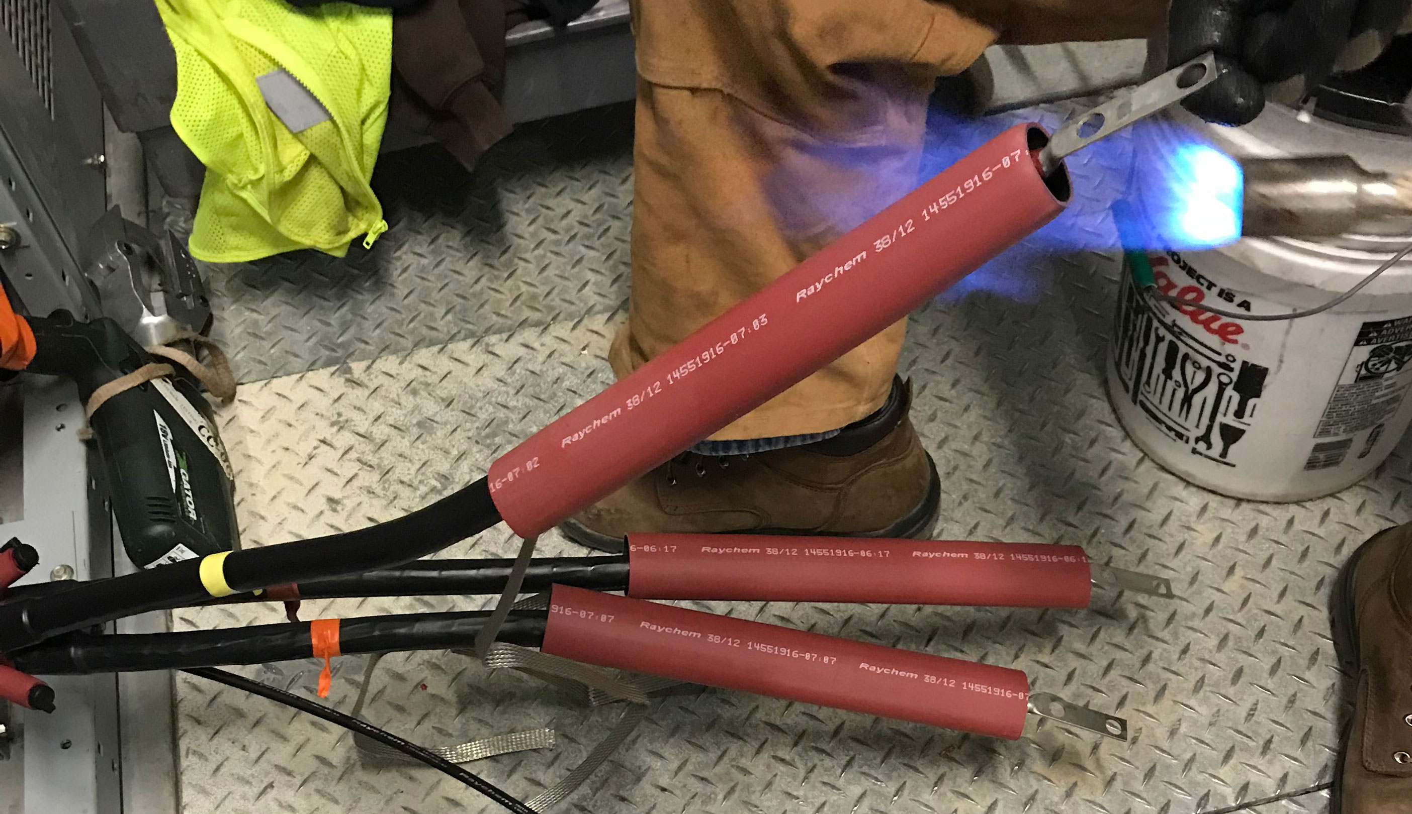
Heat shrink tubing is positioned to have heat applied
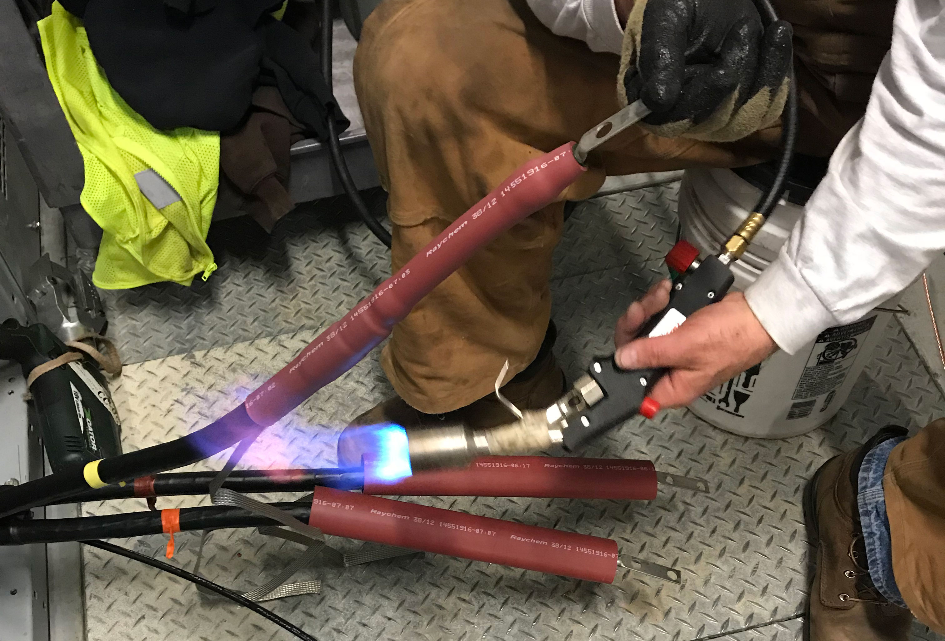
Heat must be applied evenly to ensure the tube is properly shrunk
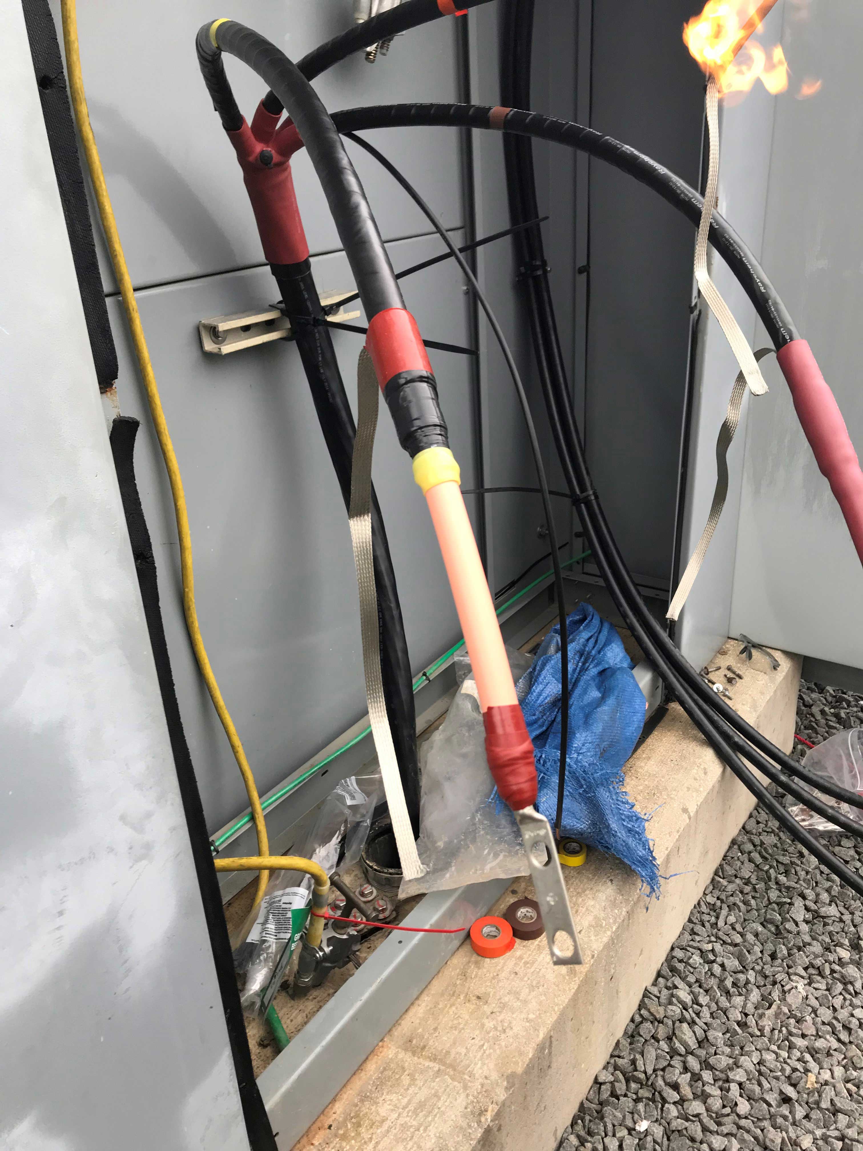
Ready for heat shrink
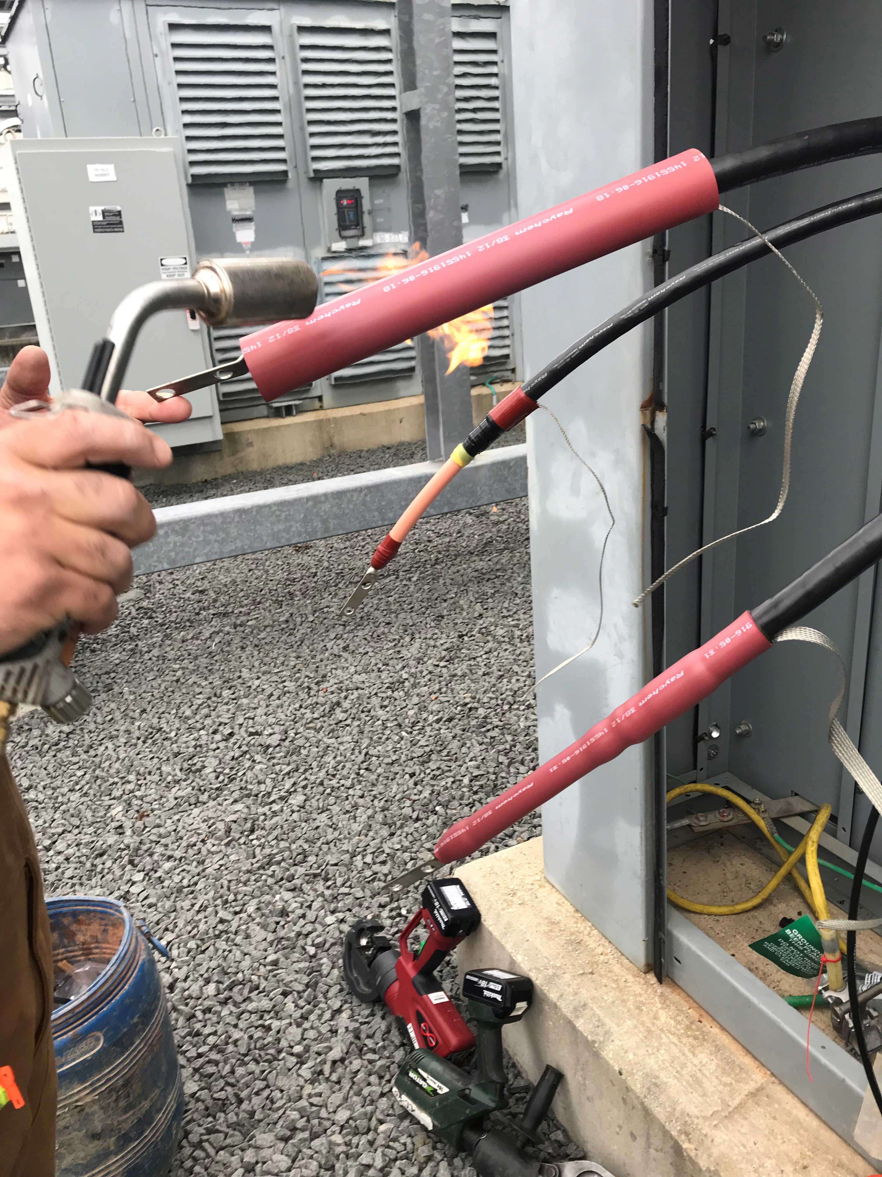
Below is a very quick demonstration of 15kV cable terminations being applied.
Photos and video courtesy of John Honigsberg and Mervin Gray. Both splicers are NCSCB certified.